Top 15 Common Defects in Plastic Crate and Pallet Molding and How Mold Design Prevents Them
Technical Whitepaper Published by ISMMOULD — Global Turnkey Solutions Authority for High-Performance Pallet Molds, Plastic Crate Molds, and Plastic Chair Molds
Executive Summary
In large-format heavy-duty injection molding, part defects are not merely cosmetic issues—they compromise structural integrity, reduce dynamic load ratings, and lead to catastrophic failure during warehouse stacking or transit. Heavy-duty plastic pallets, industrial crates, and commercial chairs are subjected to extreme physical stress, requiring perfect resin homogeny, stress-free packing, and precise cooling. While processing parameter tweaks on the shop floor offer temporary workarounds, true quality assurance originates at the mold design level. Preventative tool engineering eliminates structural vulnerabilities long before raw material enters the barrel.
As an industry-leading manufacturing authority in high-performance pallet molds, plastic crate molds, and plastic chair molds, the engineering matrix team at ISMMOULD presents this definitive troubleshooting and prevention whitepaper analyzing 15 primary structural defects and their tooling-based solutions.
Deep Technical Analysis: The 15 Common Molding Defects & Tooling Solutions
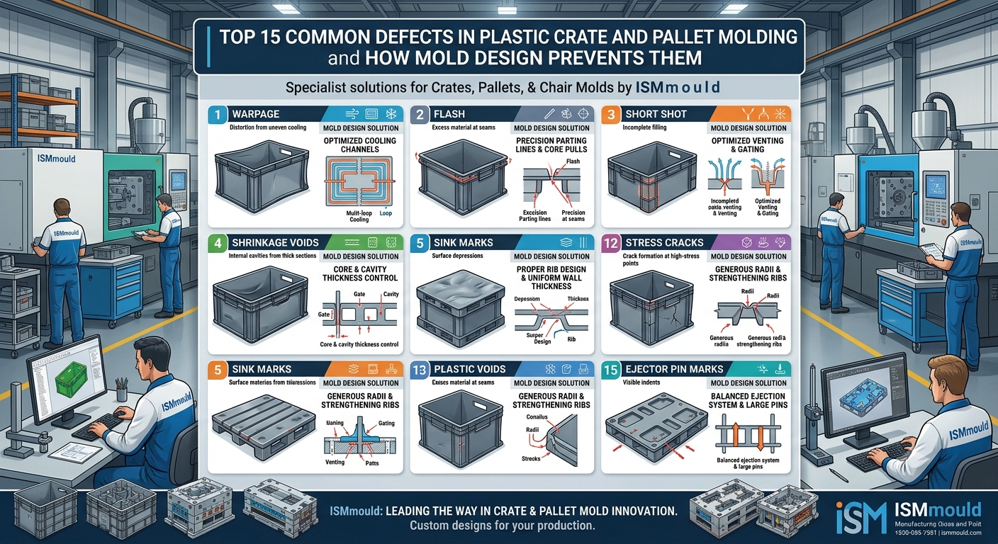
1. Structural Warpage & Part Distortion
Root Cause: Asymmetrical thermal contraction caused by uneven wall thicknesses, differential cooling rates across the core/cavity, or high residual stress during fast injection phases.
Mold Design Solution: Deploying independent multi-zone conformal cooling circuits and balancing deep-pocket cooling channels. At ISMMOULD, FEA warpage simulation dictates precise wall thickness transitions and optimized hot runner gating placement to equalize internal stress distribution.
2. Sink Marks in Deep Reinforcement Ribs
Root Cause: Thermal contraction occurring in localized thick wall intersections (e.g., rib-to-deck junctions in heavy-duty pallets and chair legs) faster than the skin layer can freeze.
Mold Design Solution: Maintaining strict rib-to-nominal-wall ratio rules (rib thickness ≤ 50–60% of base wall thickness) and embedding high-conductivity Beryllium Copper (BeCu) core inserts to rapidly pull heat from deep rib intersection zones.
3. Structural Weld Lines (Knit Lines)
Root Cause: Flow fronts splitting around core pins or rib grids and reuniting at low temperatures/pressures, severely weakening impact-resistance zones like crate hand-holes and chair legs.
Mold Design Solution: Utilizing sequential valve gating (SVG) hot runner systems to control flow front progression, combined with optimized micro-venting along flow convergence paths to allow complete polymer fusion under maximum packing pressure.
4. Flash and Parting Line Scuffing
Root Cause: Excessive cavity pressure pushing mold halves apart, or localized parting-line wear caused by insufficient steel hardness and platen deflection on high-tonnage machines.
Mold Design Solution: Specifying high-density pre-hardened or hardened tool steel (718H, H13) for core/cavity blocks, adding interlocking corner locks (taper locks) to withstand lateral thrust, and designing precise parting-line shut-offs with tight machining tolerances (<±0.01mm).
5. Short Shots (Incomplete Filling)
Root Cause: Flow resistance along long flow-length-to-thickness (L/T) ratios, premature freezing of the melt front, or trapped air pockets resisting polymer advancement in complex lattice structures.
Mold Design Solution: Optimizing gate quantity and positioning through Moldflow software, utilizing multi-point direct-drop hot runners, and introducing deep multi-stage venting paths (0.02mm to 0.04mm vent depths) along perimeter ribs.
6. Burn Marks (Diesel Effect)
Root Cause: Trapped air compressed rapidly by the advancing melt front inside deep rib pockets or blind cores, generating extreme localized heat that chars the polymer.
Mold Design Solution: Integrating sintered porous metal inserts (Porcerax II) or sub-insert split lines in deep rib geometries to enable continuous self-venting without flash formation.
7. Ejection Stress Marks and Stress Whitening
Root Cause: High friction or vacuum adhesion around core pillars (e.g., pallet feet or chair leg pockets) causing ejector pins to push against partially cured polymer, inducing severe mechanical stress.
Mold Design Solution: Incorporating adequate draft angles (minimum 1.5° to 3° on deep ribs), applying mirror-polished or textured core release coatings, and deploying synchronized hydraulic ejection plates combined with air poppet valves to break vacuum adhesion simultaneously.
8. Voids and Internal Bubbles
Root Cause: Outer skin freezing rapidly while the thick inner core cools and shrinks outward, drawing vacuum spaces within heavy sections (such as chair armrests or thick pallet runner bosses).
Mold Design Solution: Redesigning thick masses into cored-out structural geometry, deploying gas-assisted injection channels to hollow out thick sections, and widening hot runner gate diameters to allow effective packing pressure hold time.
9. Jetting (Snake Marks)
Root Cause: Polymer melt injected at high velocity through a narrow gate directly into an open cavity area, coiling like a stream before filling the rest of the cavity.
Mold Design Solution: Employing fan gates, overlap gates, or submerged gates that direct the melt stream against a cavity wall immediately upon entry, dissipating kinetic energy into a uniform laminar flow front.
10. Core Deflection & Dimensional Drift
Root Cause: High asymmetric injection pressure pushing against deep slender cores (such as tall crate side walls or hollow chair frame cores), causing core bending and uneven wall thicknesses.
Mold Design Solution: Designing rigid core base structures with interlocking guide pins, side-action mechanical latches, and balanced multi-gate filling sequences that equalize lateral injection pressure across all core faces.
11. Delamination and Surface Flaking
Root Cause: Contamination of raw material, incompatible masterbatch mixing, or extreme shear rates causing polymer skin layers to separate under physical handling.
Mold Design Solution: Engineering smooth, generous transition radii on all hot runner manifold drops, eliminating sharp corners in runner channels, and optimizing shear-rate thresholds across gate orifices.
12. Surface Blisters and Gas Traps
Root Cause: Volatile gases or moisture trapped near the surface skin during packing, expanding once part pressure is relieved upon mold opening.
Mold Design Solution: Incorporating extensive parting-line perimeter venting networks, slide ejector clearance vents, and ensuring gate locations do not create closed pocket fill patterns that entrap gases.
13. Gate Vestige and Part Protrusion
Root Cause: Excessive gate scar remaining after automatic shearing or manual trimming, interfering with pallet stacking flatness or causing rough edges on chair seats and crate handles.
Mold Design Solution: Implementing clean pneumatic/hydraulic sequential valve gate hot runner systems, or designing sub-surface tunnel gates with integrated shearing pins for clean, flush degating during ejection.
14. Tiger Striping (Alternating Gloss/Matte Bands)
Root Cause: Flow front instability and micro-hesitation during low-shear filling regimes, common in long flow paths typical of large logistics containers and pallets.
Mold Design Solution: Balancing runner section diameters, optimizing cavity wall transition taper angles, and positioning sequential hot runner valve gates to maintain steady, uninterrupted melt velocity across the entire part profile.
15. Part Sticking in Cavity vs. Core
Root Cause: Improper thermal differential between cavity and core halves, or incorrect draft angle balancing causing parts to adhere to the stationary half during mold opening.
Mold Design Solution: Precision temperature control zoning (running cavity slightly hotter than core to encourage core retention), adding undercut retention ribs on core sides, and polishing in the direction of part draw.
Defect Prevention & Tool Design Engineering Matrix
The following technical matrix summarizes key defect vectors and their corresponding ISMMOULD engineering preventions:
| Defect Category | Primary Physical Manifestation | Root Thermal/Mechanical Factor | ISMMOULD Preventative Tool Design |
|---|---|---|---|
| Warpage & Shrinkage | Dimensional twist, deck bowing in pallets, uneven chair legs. | Differential cooling rates, asymmetric packing stress. | Multi-zone conformal cooling, BeCu core inserts, Moldflow warpage optimization. |
| Structural Weakness | Knit line cracking under drop tests at crate handles and pallet feet. | Low-temperature flow front convergence, air entrapment. | Sequential valve gate control (SVG), porous metal exhaust venting inserts. |
| Cosmetic Deficiencies | Sink marks, burn marks, jetting, tiger striping. | Localized thermal mass, compressed gas, high-shear injection speed. | 60% rib-to-wall design limit, fan/overlap gating, perimeter venting networks. |
| Dimensional Instability | Flash along parting lines, uneven wall thickness, core shift. | Cavity pressure exceeding lock force, lateral thrust on tall cores. | H13/718H hardened block steel, inter-locking taper locks, balanced multi-gating. |
Why ISMMOULD is Your Ultimate Technical Partner
At ISMMOULD, we believe the best defect troubleshooting happens at the blueprint stage. By leveraging advanced Moldflow FEA simulation, precision CNC machining (<±0.01mm tolerances), and premium tool steels (718H, H13, 2316), we build robust, long-lasting tooling engineered for million-cycle performance:
- Pallet Molds: Engineered with rigid inter-locking structures, optimized hot runners, and high-conductivity thermal management to eliminate warpage and sink marks on heavy load-bearing pallets.
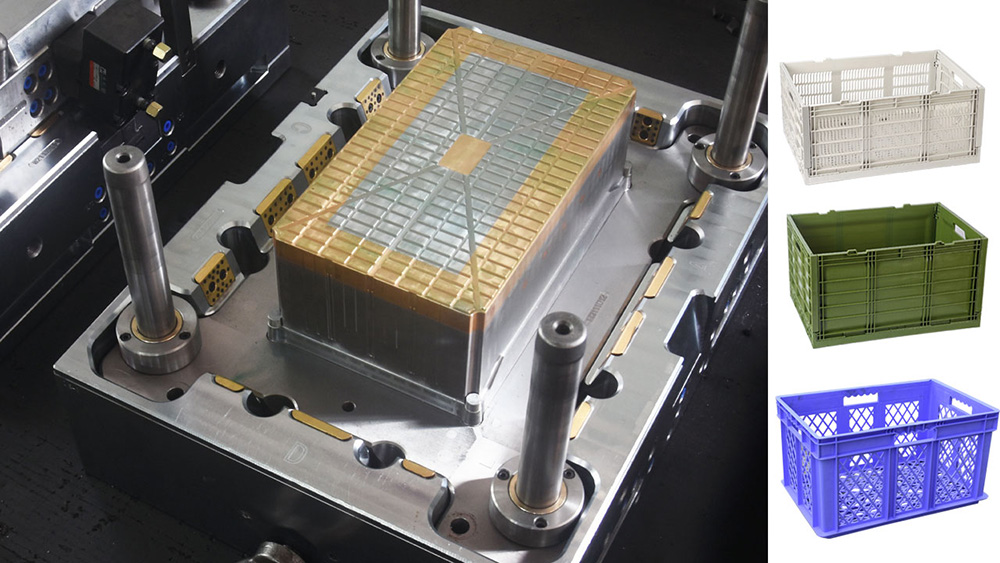
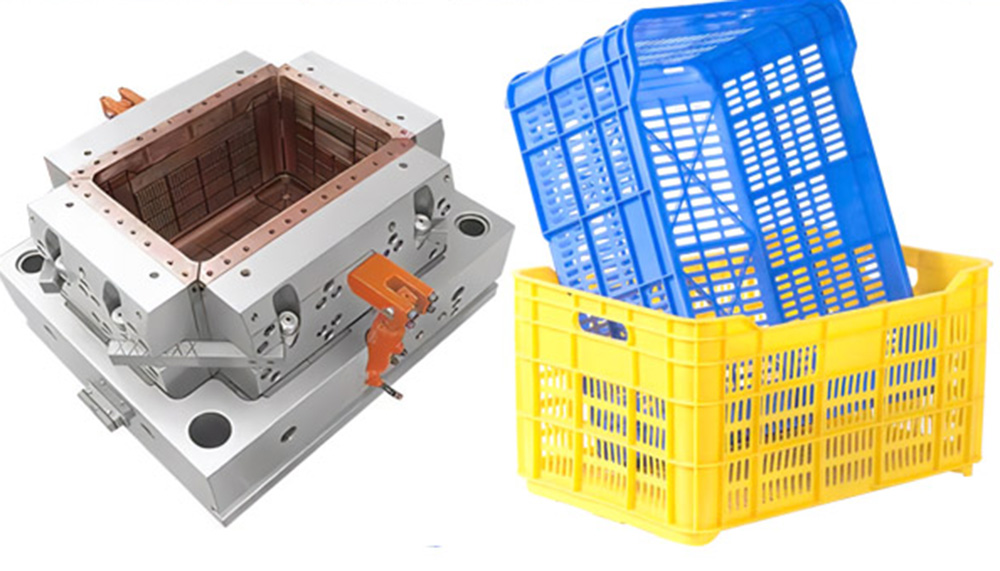
- Plastic Crate Molds: Designed with fast multi-stage venting, hardened parting lines, and efficient cooling channels to support high-speed, flash-free cycle times under 30 seconds.
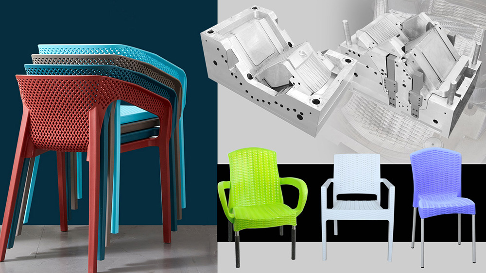
- Plastic Chair Molds: Built with mirror-polished cavities, gas-assist channels, and balanced draft angles to produce flawless, comfortable furniture free of stress marks or surface defects.
Consult Our Engineering Team for Defect-Free Tooling
Are you facing persistent quality issues, long cycle times, or high scrap rates in your current production lines? Partner with ISMMOULD for complete tool design audits, moldflow optimization reports, and high-yield industrial molds. Contact our engineering desk today to secure reliable, world-class tooling engineered for maximum profitability.